Do you have an Arduino or ESP32 project that requires remote control of a mains-voltage device—such as an air conditioner or lamp—via MQTT? Here’s the challenge: most household electronics need significantly higher voltages to operate, while your board only runs on 3.3 to 5 volts. How can one safely close that gap, then?
This is where relay modules are useful in this situation. These small, inexpensive modules function as electrical switches, so you can easily control high-voltage appliances with your low-power ESP32 or Arduino via a MQTT connection (or anything else).
This guide will demonstrate how to link your ESP32 to a one-channel relay module and use MQTT to connect it to the IoT Stadium platform. By the end, you'll be able to remotely turn on and off appliances like motors and lamps. Let's take a brief look at how a relay functions before getting into the wiring and programming.
How Does a Relay Work?
A relay is essentially an electrically operated switch. It uses a small control signal to open or close a separate high-voltage circuit, allowing low-power devices like an ESP32 or Arduino to control appliances that require much more power.
Inside a relay, there are three main components:

https://electrosome.com/electromagnetic-relay/
- Coil – When energized by a low-voltage signal, it generates a magnetic field.
- Common (COM), Normally Open (NO), and Normally Closed (NC) contacts – These act as the switch terminals that connect or disconnect the high-voltage circuit.
- Armature – A movable lever that switches between NO and NC depending on whether the coil is energized.
Here’s how it works in action:
- When the coil is off, the armature rests on the NC (Normally Closed) terminal, keeping the circuit closed (or open, depending on wiring).
- When the coil is energized by your ESP32’s signal, the magnetic field pulls the armature to the NO (Normally Open) terminal, changing the state of the circuit.
This mechanism allows you to control devices running on high voltage without your microcontroller directly handling the dangerous current.
Now that you understand how a relay works. Let’s take a closer look at what the ESP32 is and why it’s an excellent choice for this project.
What is ESP32 and Why is it Used?
The ESP32 is a powerful and cost-effective microcontroller with built-in Wi-Fi and Bluetooth capabilities, making it ideal for Internet of Things (IoT) projects. Unlike traditional Arduino boards, the ESP32 can connect directly to your network without additional hardware, which is crucial when you need to send or receive commands via an MQTT connection.
Here’s why the ESP32 is a great choice for this project:
- Wi-Fi and MQTT-ready – Directly connects to IoT platforms like IoT Stadium.
- Dual-core processor – Can handle multiple tasks, such as sensor reading and communication, without lag.
- Low power consumption – Suitable for always-on applications.
- Multifunction I/O pins – Can easily drive relay modules and interface with various sensors.
With its network connectivity and strong hardware specs, the ESP32 is the perfect bridge between your relay module and the IoT Stadium platform.
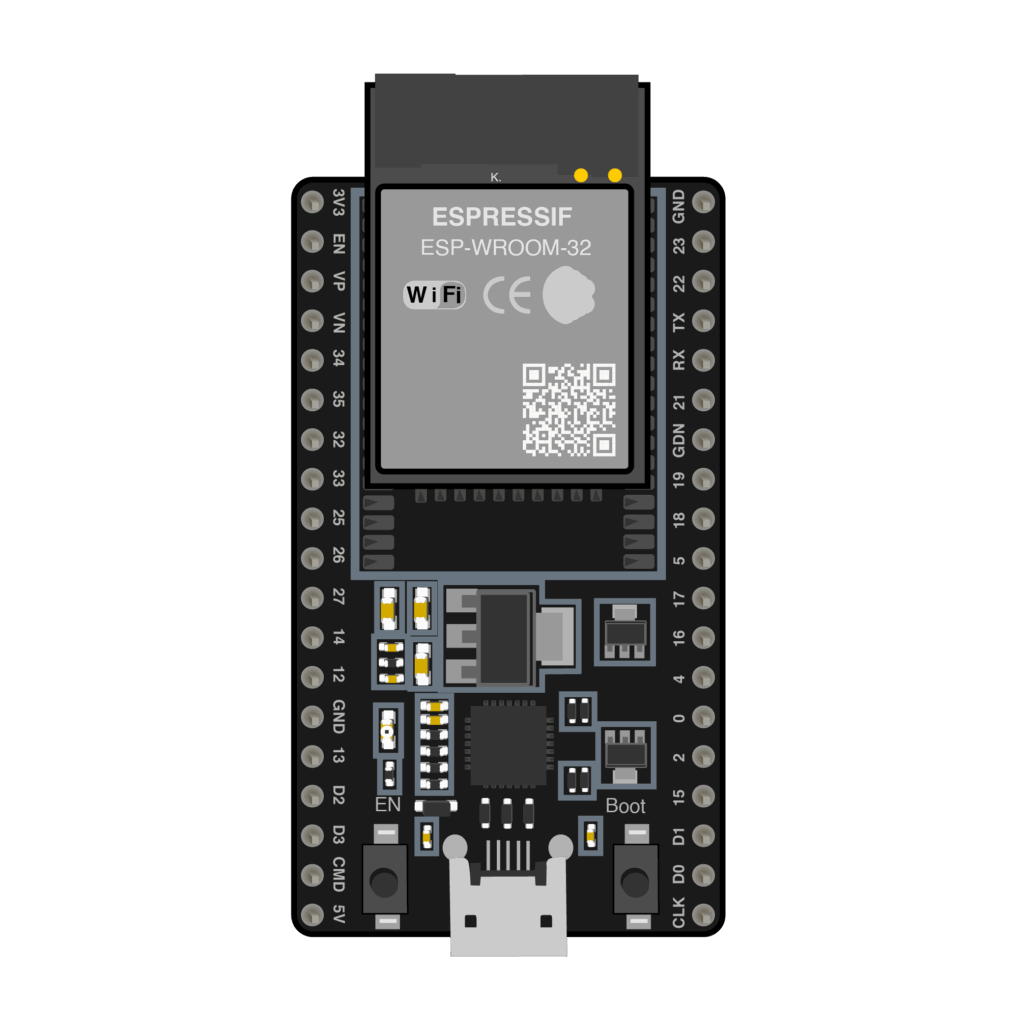
Wiring Diagram ESP32 with Relay Module
Now let’s put the hardware together. Below is the wiring diagram that shows how to connect your ESP32 to a one-channel relay module. This connection allows your ESP32 to control the relay safely using its GPIO pins.
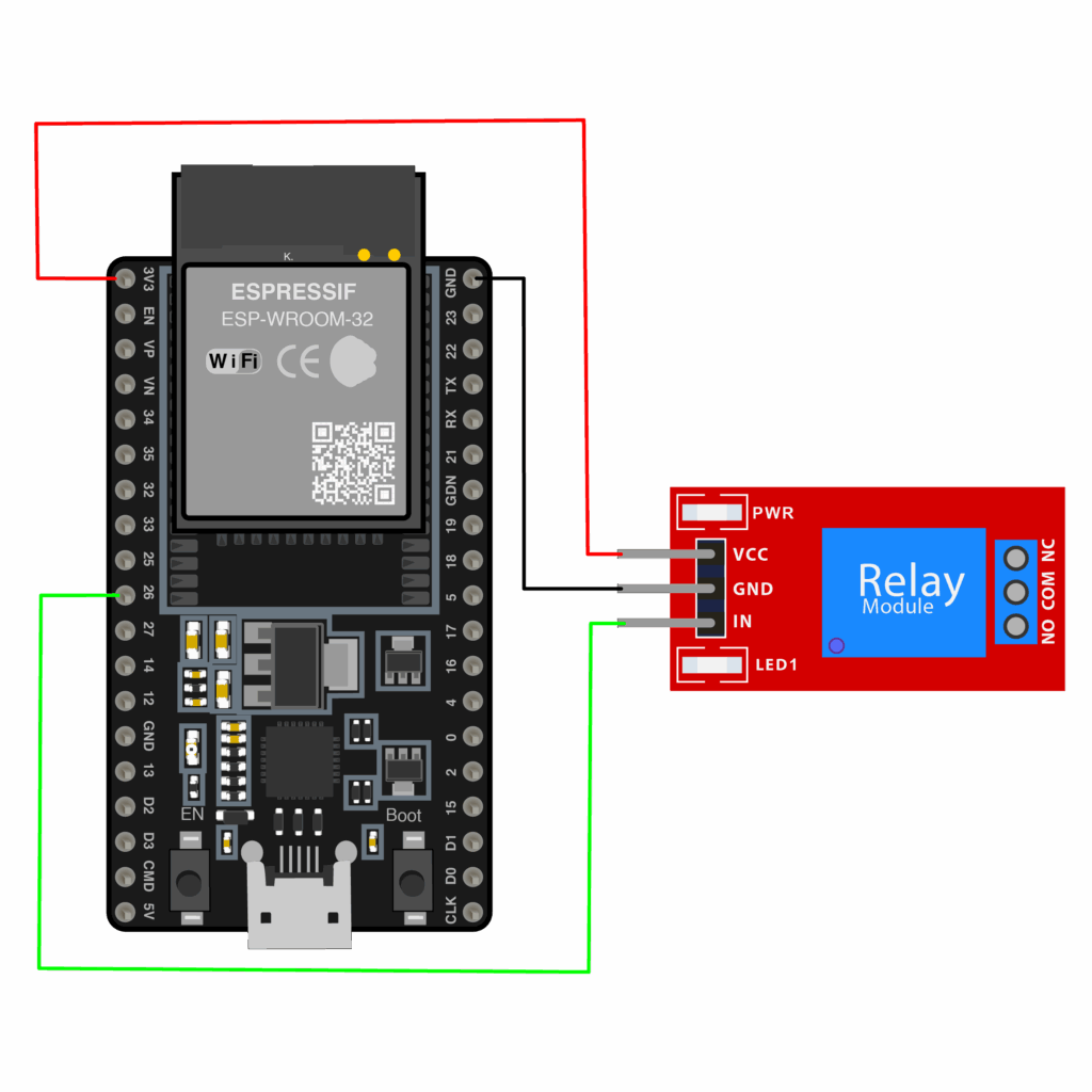
Key connections to make:
| ESP32 Pin | Relay Module Pin |
| GND | GND |
| 3V3 | VCC |
| GPIO 26 | IN |
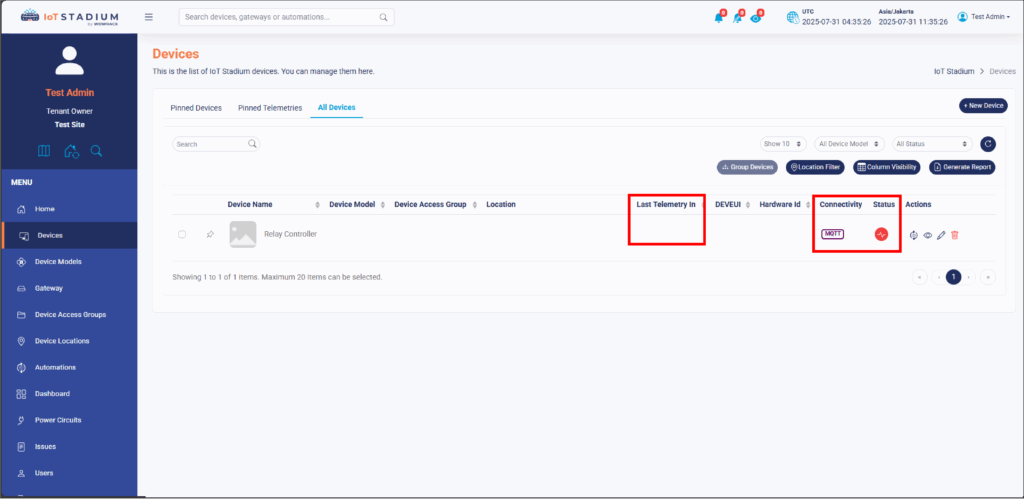
Adding To the IoT Stadium
After wired the ESP32 with the relay module, you need to add your device to the IoT Stadium platform.
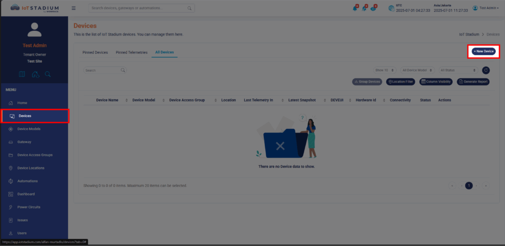
1. Go to IoT Stadium platform.
2. Go to Device tab and click on New Device.
3. Set the name for your device.
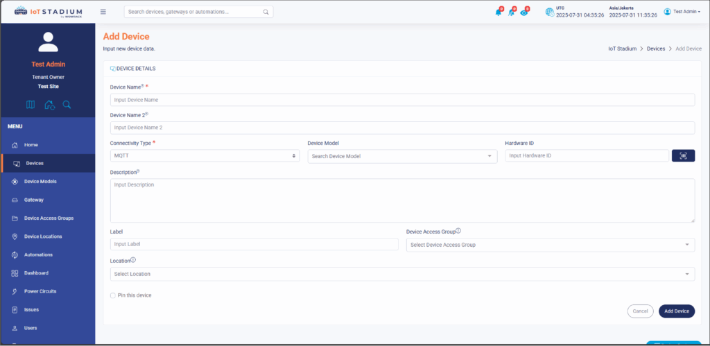
4. Set the Connectivity Type as MQTT.
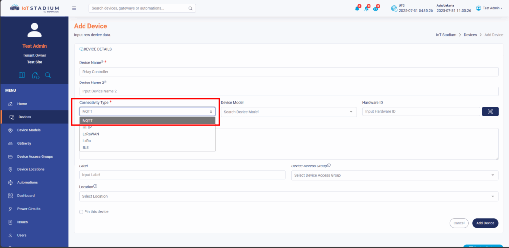
5. Click Add Device when done.
Once your device has been successfully added to the IoT Stadium platform, you’re ready to move on to the next step: programming your ESP32 to connect to the platform and control the relay.
Programming ESP32 for MQTT Relay Control
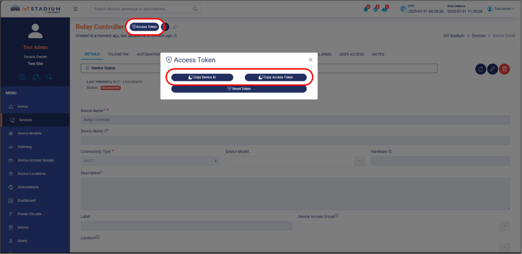
Indeed, your device has been added but it still not connected to any gateway, so you need to configure the MQTT connection.
1. Click on your device.
2. Click on Access Token.
3. Click on Copy Device ID and Copy Access Token. Paste both on your Notepad.
*Note: Both will be used on your code.
4. After this, you can open your Arduino IDE.
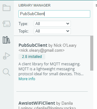
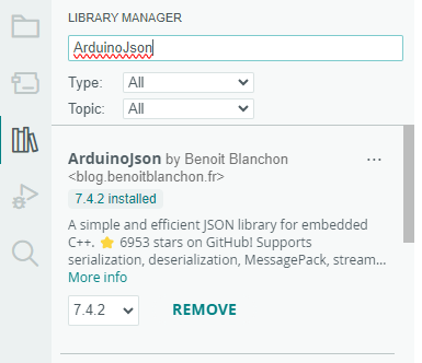
5. Install PubSubClient and Arduino Json library.
6. After that, you may copy and paste the code down below.
#include <WiFi.h>

#include <PubSubClient.h>

#include <ArduinoJson.h>

const char* ssid = "your-wifi-name";  //Wifi SSID

const char* password = "password??";   //Wifi Pass

const char* mqtt_server = "telemetry.iotstadium.com";

String deviceId = "-";   //Paste the Device ID here

String accessToken = "-";  //Paste the Access Token here

WiFiClient espClient;

PubSubClient client(espClient);

const int relay = 26; // Pin Relay

void mqttCallback(char* topic, byte* payload, unsigned int length) {

Serial.print("Message arrived [");

Serial.print(topic);

Serial.print("] ");

for (int i = 0; i < length; i++) {

Serial.print((char)payload[i]);

}

Serial.println();

payload[length] = '\0';

String message = (char*)payload;

StaticJsonDocument<256> doc;

DeserializationError error = deserializeJson(doc, message);

if (error) {

Serial.print(F("deserializeJson() failed: "));

Serial.println(error.c_str());

return;

}

const char* relayState = doc["relay"];

if (String(relayState) == "on") {

Serial.println("Relay-On");

digitalWrite(relay, LOW);// Relay we used Active LOW

}

if (String(relayState) == "off") {

Serial.println("Relay-Off");

digitalWrite(relay, HIGH);

}

}

void setup() {

Serial.begin(115200);

pinMode(relay, OUTPUT);//Init Relay

digitalWrite(relay, HIGH);//kondisi pertama relay mati

WiFi.mode(WIFI_STA);

WiFi.begin(ssid, password);

while (WiFi.status() != WL_CONNECTED) {

delay(500);

Serial.print(".");

}

Serial.println("Succesfull Connect with WiFi");

client.setServer(mqtt_server, 1883);

client.setCallback(mqttCallback);

if (client.connect(deviceId.c_str(), deviceId.c_str(), accessToken.c_str())) {

String Topicsubscribe =deviceId + "/controller";

client.subscribe(Topicsubscribe.c_str());

Serial.println("Succesfull Connected with IoTStadium");

}

}

void loop() {

client.loop();

delay(1000);

}
7. Then you can upload the program on your board.
8. You can switch to controller
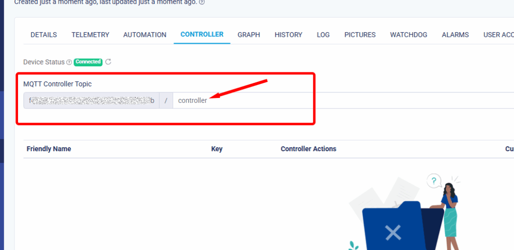
9. As you can see, you can add your own new controller telemetry on this platform. You can see at the box next to the MQTT Controller Topic.
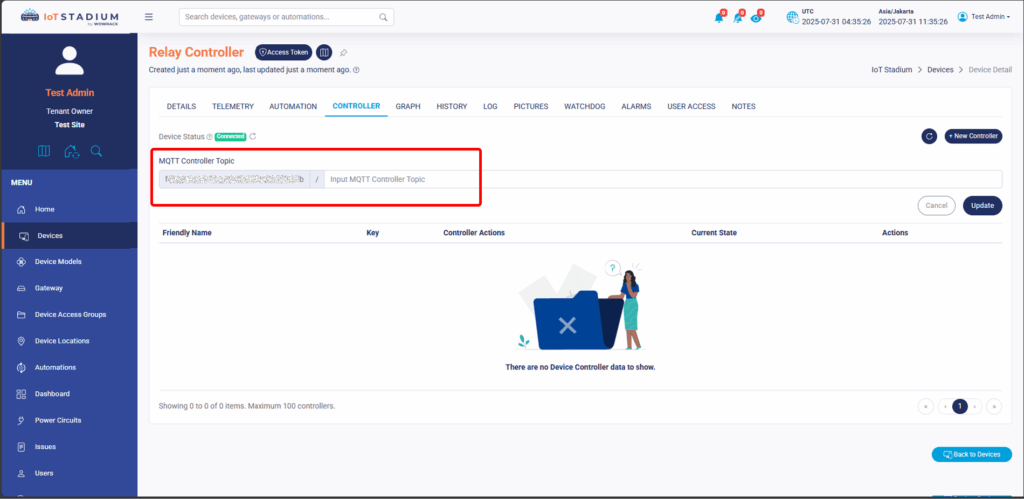
10. Since we use String Topicsubscribe = deviceId + "/controller"; so if you want to add the new controller you need to type it as “controller”. Then click Update when done.
11. Click on New Controller.
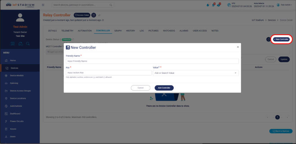
12. Because we use const char* relayState = doc["relay"]; so we need to set the key as“relay” while the value the value you may chose it for “on” and “off”.
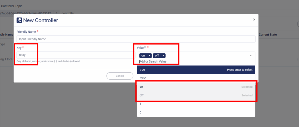
13. Click Add Controller when done.
With this, you can use your controller remotely using IoT Stadium.
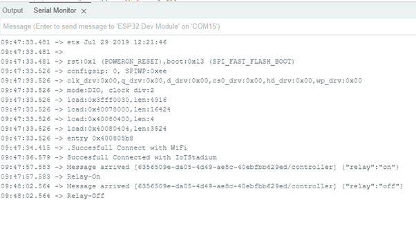
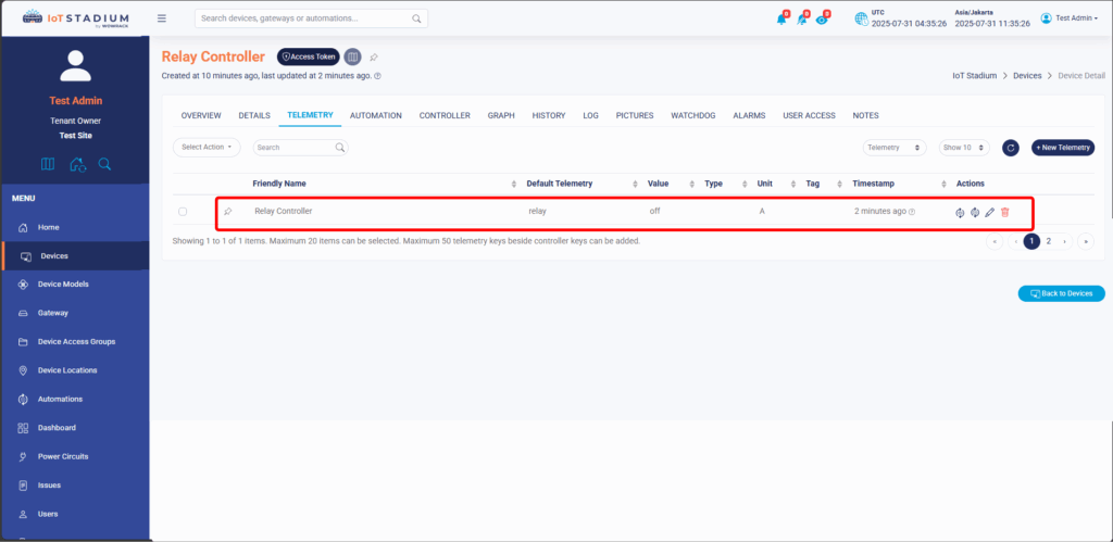
*PS: Don't forget to check your serial monitor and Telemetry tab to match the condition.